Programming
Written in micropython, our codebase is devised of scheduler based tasks written as finite state machines with shared variables. Each peripheral has its own class with task class to handle its integration.
Tasks
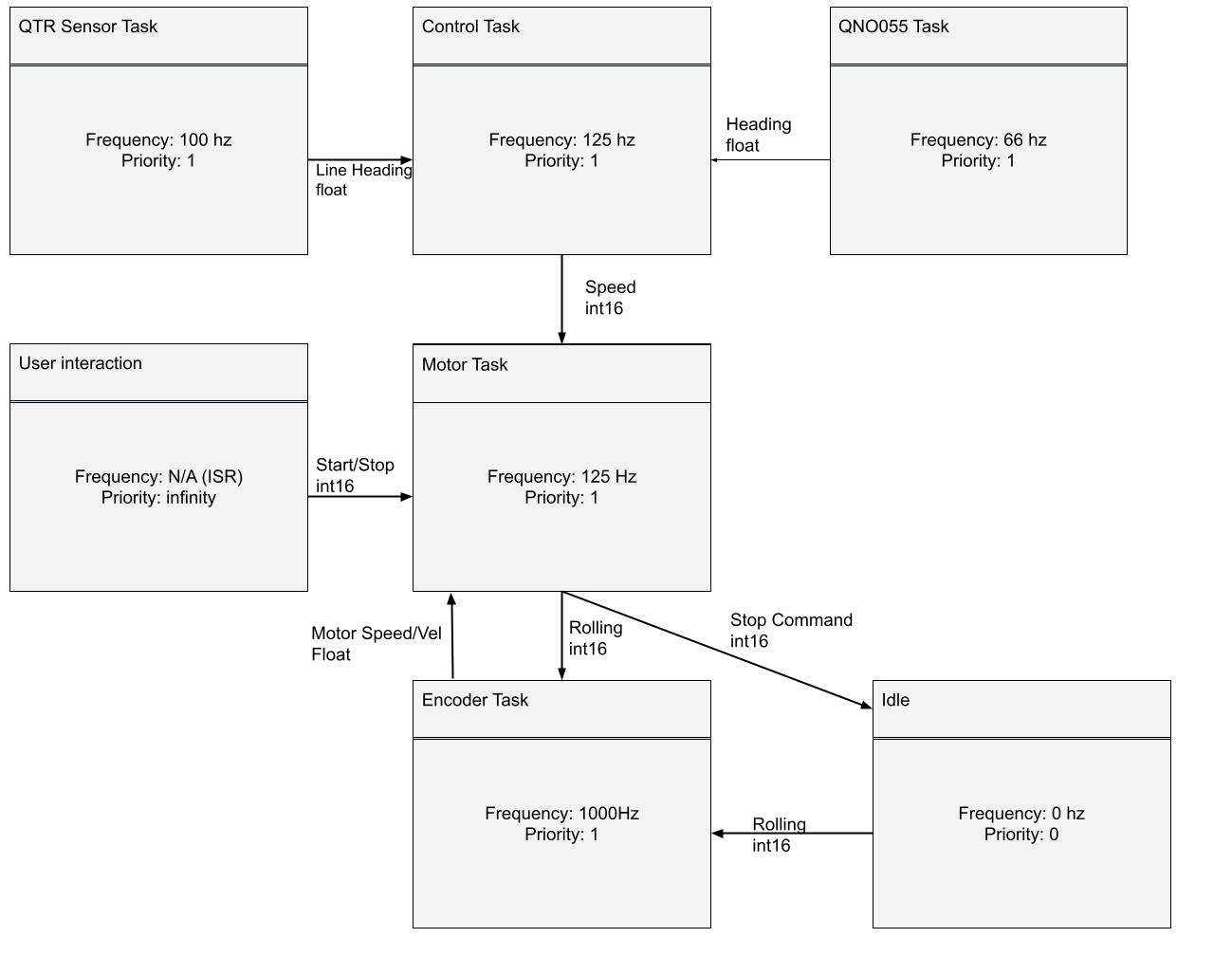
We use Cal Poly’s ME405-Support libraries which provide the python files for implementation of tasks, shares and queues. This allows us to time when we get sensor readings, drive motors and use our controller. Shares allow us to have variables that different tasks can use and change. For example, our controller task can adjust the motor speed share which the motor task reads and uses to drive the motors to achieve a goal.
Finite State Machines
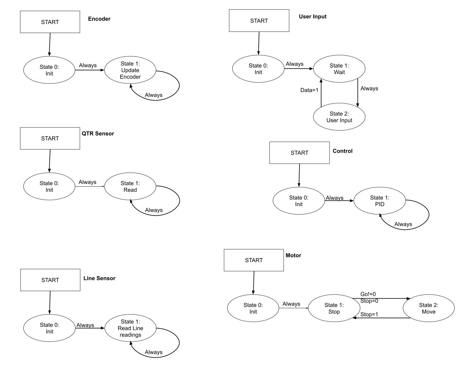
Each our tasks use generators written as finite state machines (FSM) Idk why but this FSM isnt updating from old jpg
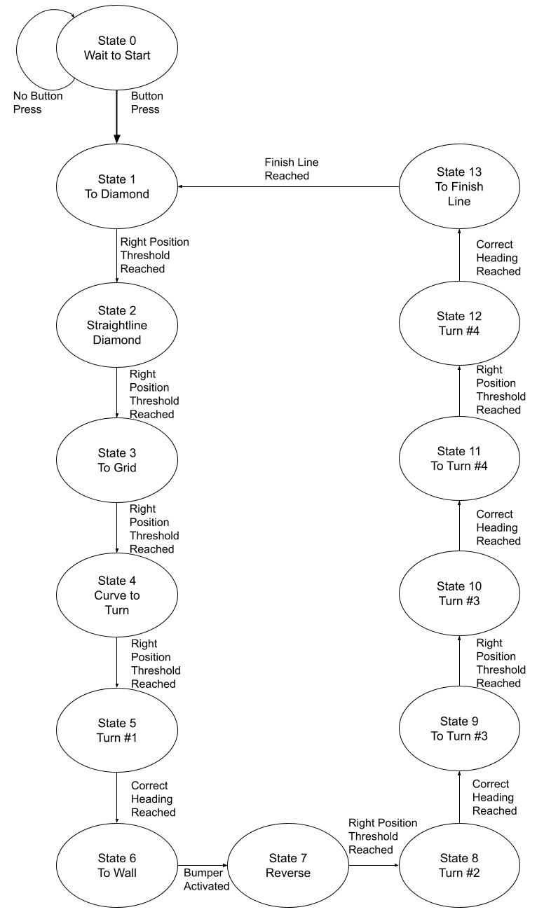
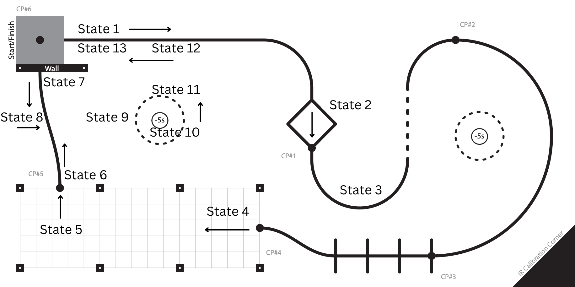
In main, we use a FSM to complete the course. It features hardcoded encoder position thresholds which jump between line following, heading following and full reverse modes.
Course FSM
Line Sensing Methods
Our line sensor features an array of light sensor that all produce a reading that can be normalized to 0 to 1 with a 1 being black. If the line is perfectly below the sensor, we get a ‘normal’ distribution with the middle sensors reporting a 1 while each sensor moving outwards has less black line under it. We use this theory to find the centroid of our sensor array which we can compare to the centroid of a perfectly centered line.
where \(q_i\) is the sensor value and \(x_i\) is the sensor location
This is sent to our controller which tells the motors what to do to realign the robot with line.