2-DoF Origami Worm
Overview
This project started as a Cal Poly SURP in 2023. I joined in the beginning of 2024. I worked under Dr. Mohammed Hasan with undergraduate students Micheal Freeman, Conor Schott, Carter Josef, and Col Cook.
Most of my work was on getting the robot to move well. The origami pattern was already created and worked well. We needed to program it for cyclic motion and keyboard inputs. I worked to characterize the stiffness of different origami springs and generalize it to certain metrics of the springs.
There were many developments in the material of the origami, the design of the friction pads, the material of the string, and the method of control.
We published a paper at the 2024 ASME IDETC-CIE where Michael and Conor presented our work.
The paper can be found the ASME Website.
Following this, I continued work on the origami worm. Because of the properties of origami structures, origami robotics are often hard to reproduce. Our robot struggled with this: the motion was inconsistent, and it was difficult to test new worm angles and friction pads. As part of ME-400 (Special Problems for Advanced Undergraduates), I redesigned the robot. I redesigned all the motor mounts, developed a clamping system to attach the origami spring, created a fast-mounting system for 3D-printed directional friction pads, and swapped from servos to DC motors controlled by an analog joystick.
Currently, we are still working on consistent forward motion. This includes designing new 3D printable ideas, trying new materials like PDMS and trying electromagnets.
Chronological Details:
Design
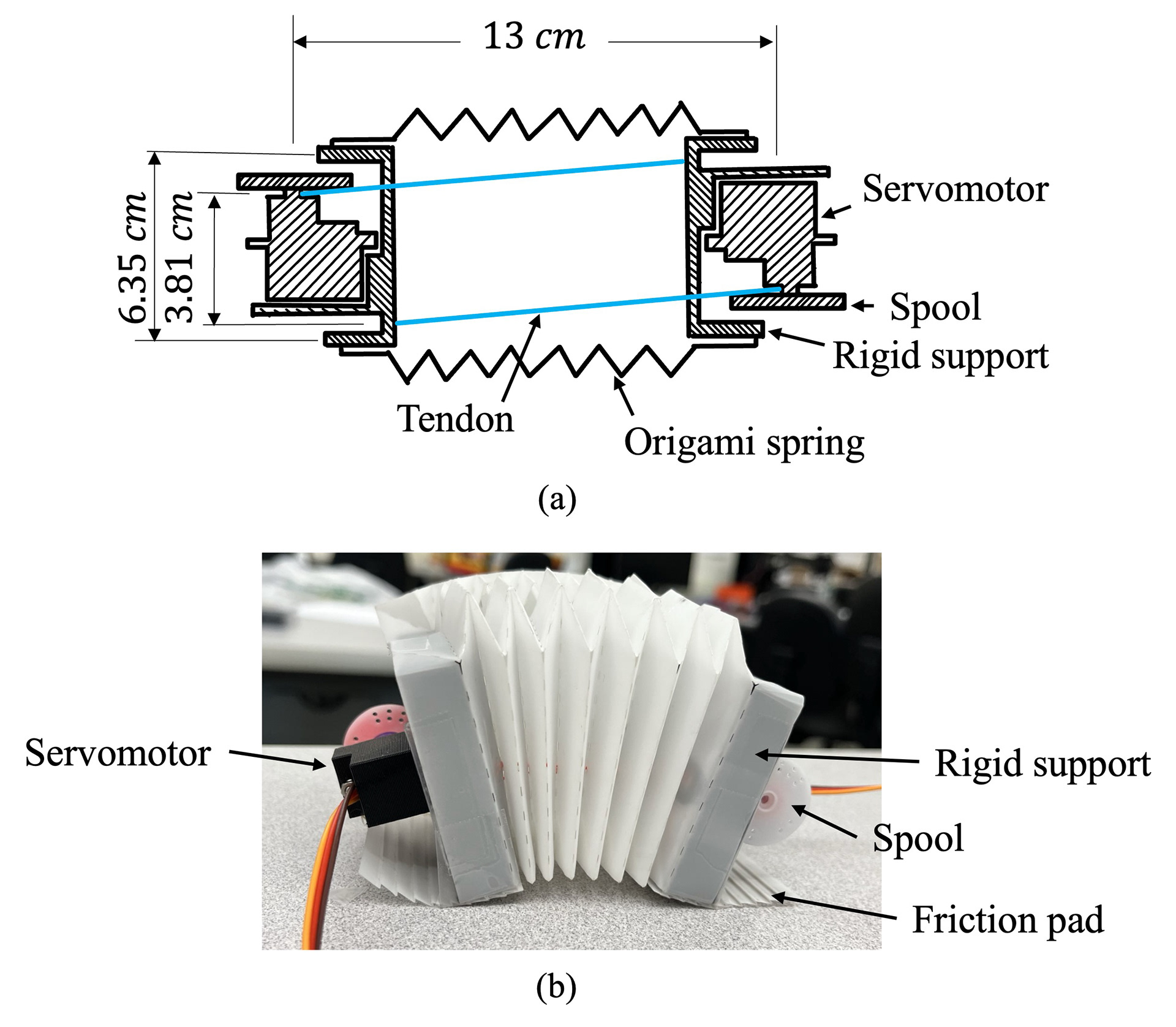
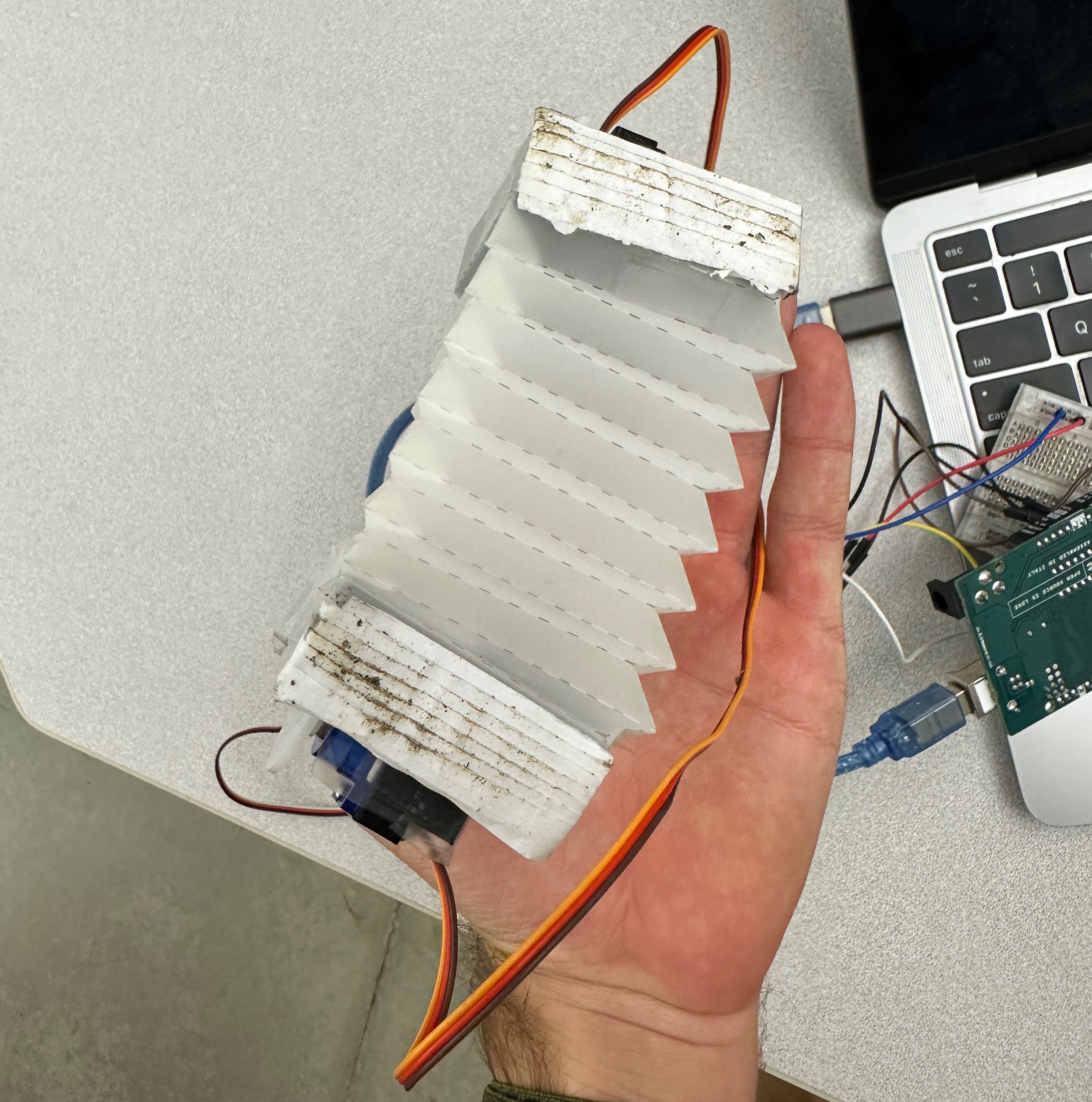
The robot consists of two servo motors that sit on opposite sides of the robot. They have a tendon that connects directly to the other side that is off-center. This allows the robot to compress and decompress in unique ways which can illicit forward motion and turning motion. The friction pad on the bottom of each support makes the forward motion possible.
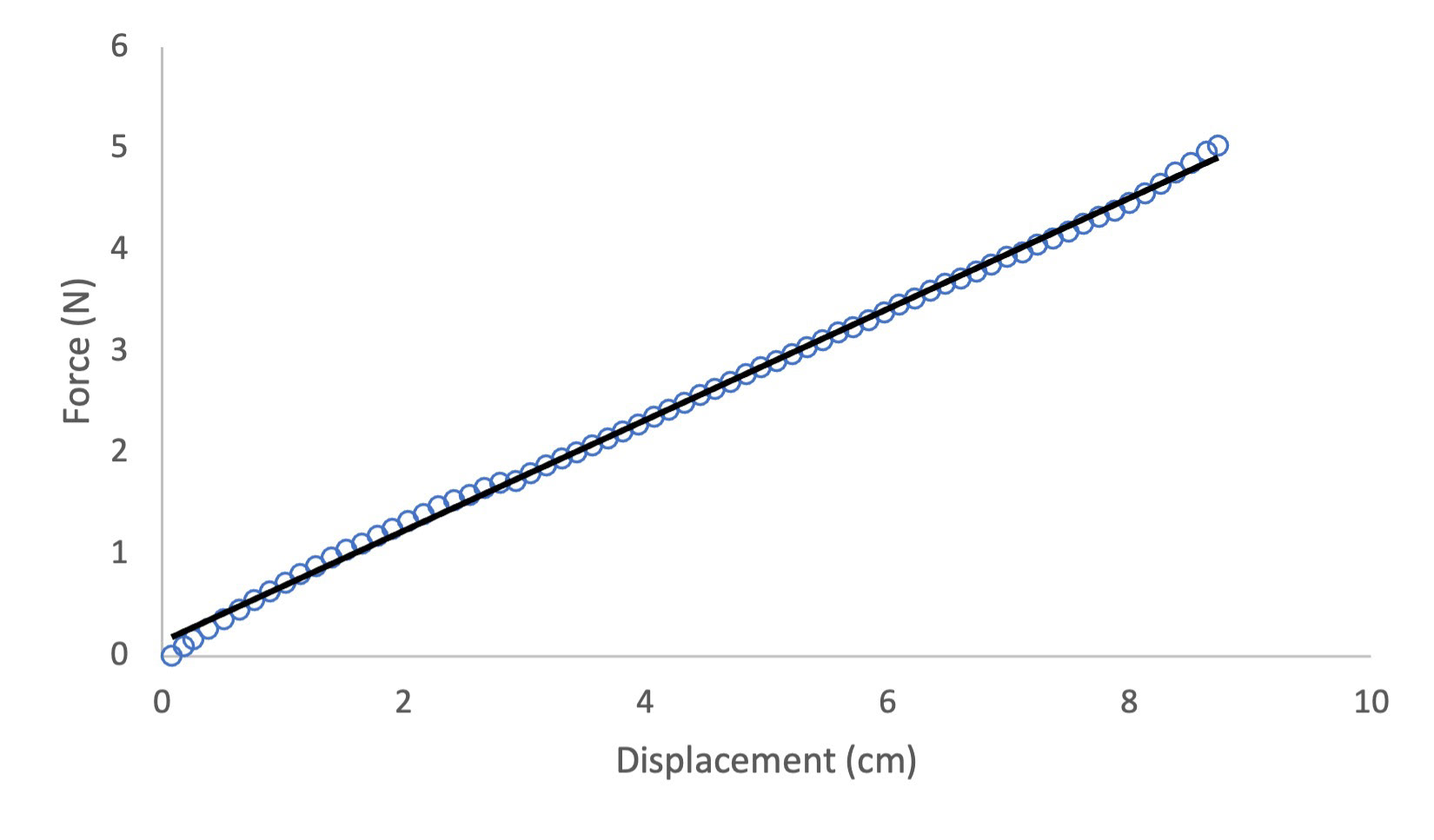
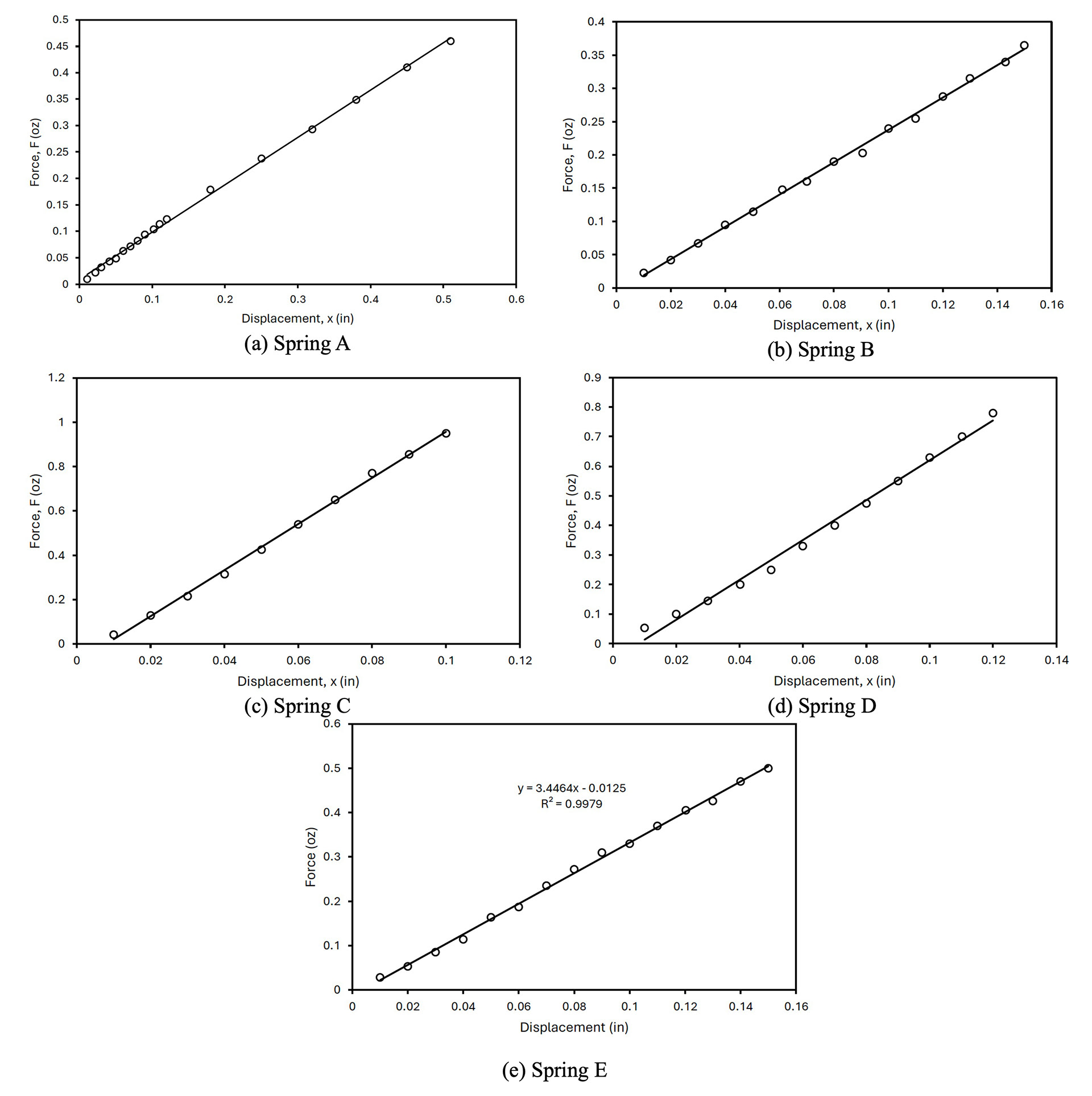
Stiffness Testing
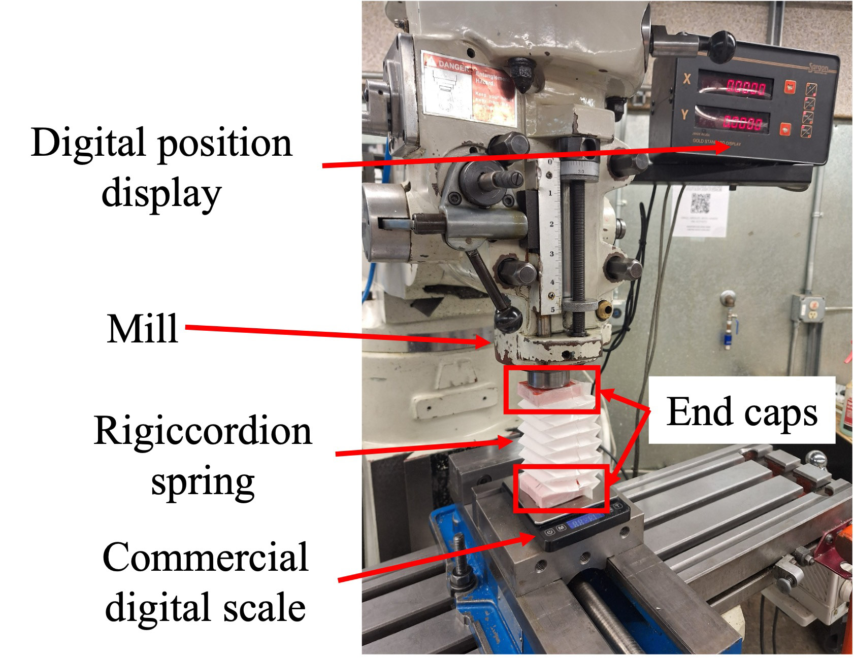
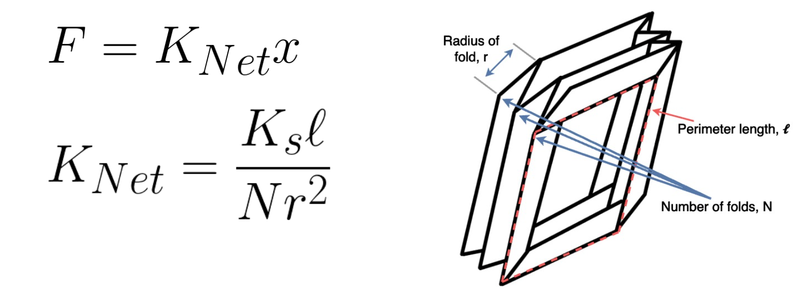
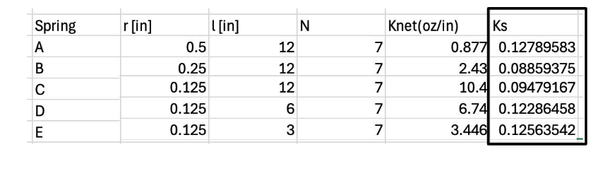
To characterize and generalize the stiffness of the Rigiccordion spring, we completed stiffness tests using a mill and commercial scale. This allowed us to show the linearity of the spring’s stiffness. We also developed empirical correlations to try to predict the stiffness of different size Rigiccordions. These correlated relatively well using the perimeter of the spring, the number of folds, and the radius of each fold along with a material factor.
Directional Friction Pads
After weeks of watching the robot sliding randomly, we came up with the idea of directional friction pads. These were to slide in one direction and hold in the other which would let the rear support come forward as the front support stayed still and vice versa.
Our first success used folded paper pads, as seen in the video at the top. These worked well but slowly disintegrated, and only worked on very specific surfaces. However, this success gave us hope that smooth and consistent motion was possible without the use of any rotary mechanisms for traction.
Robot Redesign
Previously, the origami spring was attached with tape to the supports. During testing, the spring would slip and was difficult to detach and reattach. A new mechanism was designed to allow quick on/off and one that would hold the spring in place well.
Clamping System
The new system has a clamp that sandwiches the spring between two plastic pieces. The clamp has edges that when fully put together will add extra resistance to coming apart.

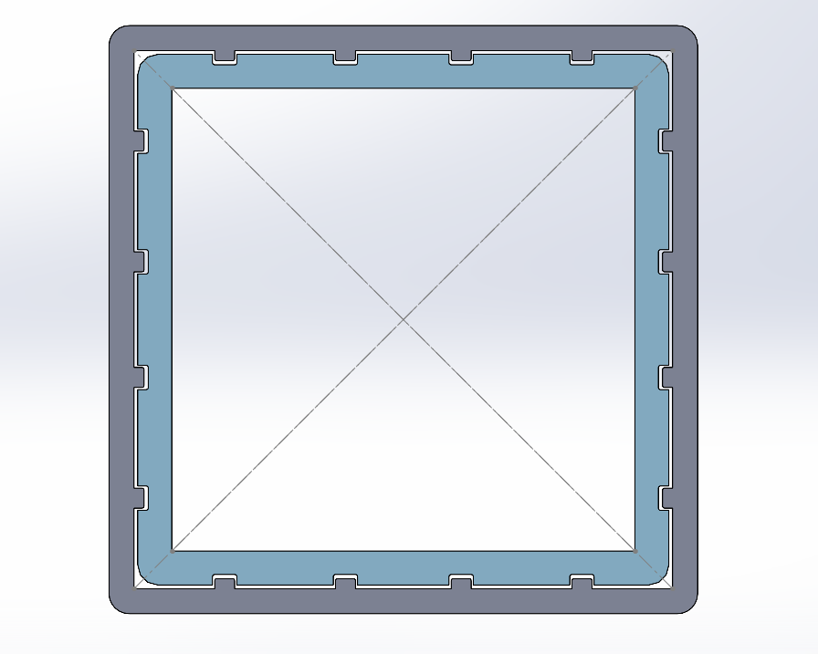
Friction Pad Fast-mounting System
Since the new spring attachment system had an outer shell, this opened up the opportunity to add a way to attach friction pads directly. On the old system, friction pads were taped on. The new system used rails on the friction pads that would slide into a slot on the outer shell of the clamp. The rails are 1.3 mm thick, and the slot is 1.5 mm thick.
Servos to DC Motors
The original design used continuous rotation servos for actuation. These were quick to implement, cheap, and in the lab. The servos were small and weak so they sometimes could not compress the asymetrical spring at the same rate. Also, they had a small plastic shaft with a star design. This made it very difficult to 3D print new parts that would couple securely.
The right DC motor could solve all the problems with the servos. We needed a DC motor with an encoder that was strong enough to compress the robot completely. A quick calculation was done to estimate the maximum torque necessary to hold the robot in full compression and to compress the robot at a rate similar to the previous robot. Stiffness data was used from the previous paper.
A Pololu micro-geared DC motor was selected. An option with a 298:1 gear ratio fulfilled both the torque and speed. This motor was also very small and had an encoder built-in.
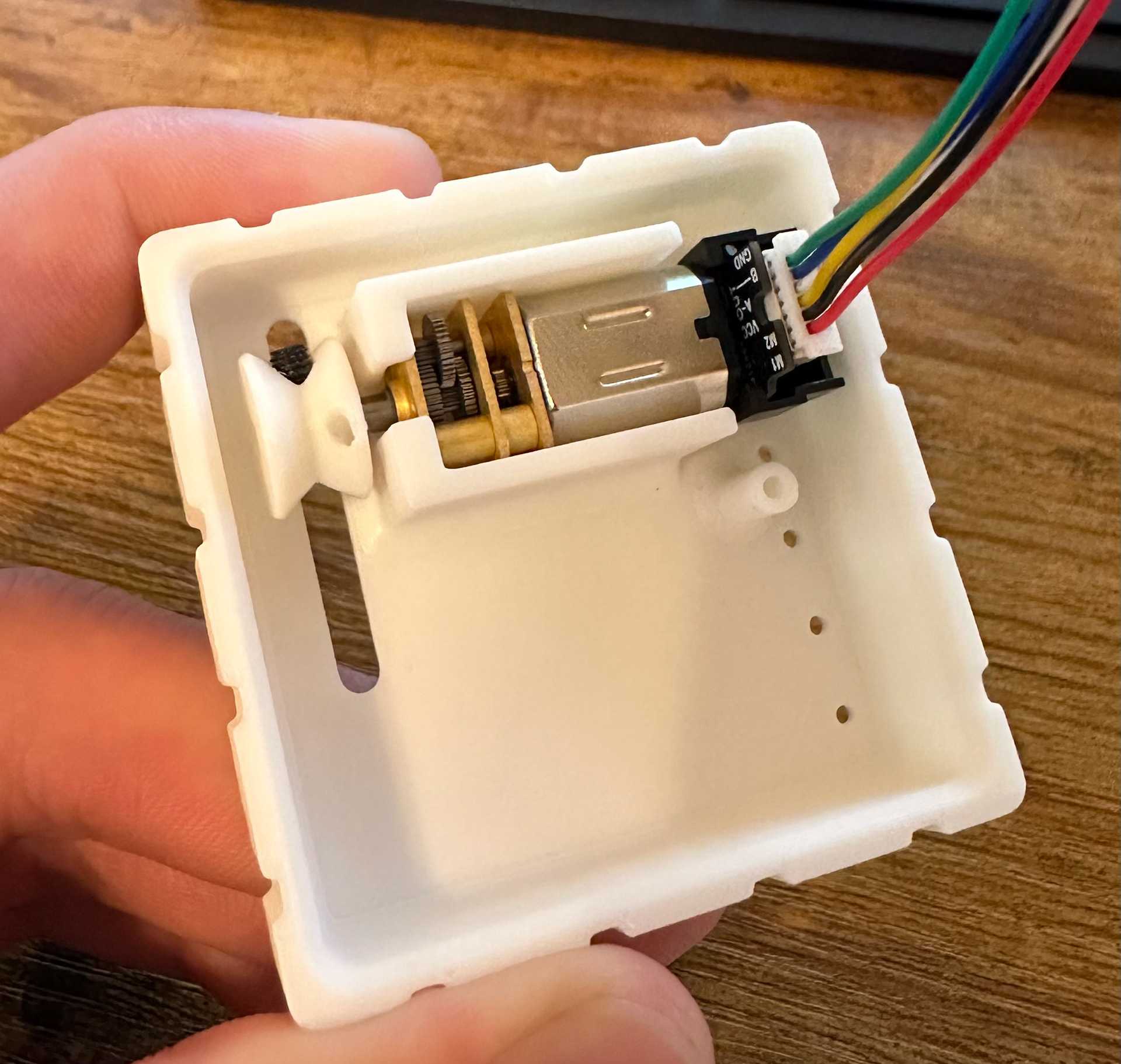
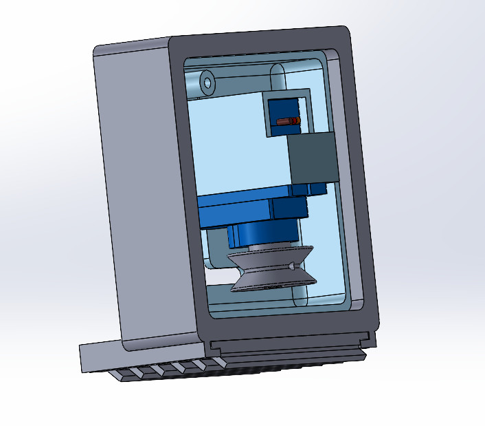
Since new motors were used, the motor mounts needed to be redesigned. The mounts were designed to be in line with the other side’s connection and were to be as minimal as possible. Also, the mount features a spot for a screw to be screwed in to hold the other side of the tether. There were many different spots where the tether could be attached.
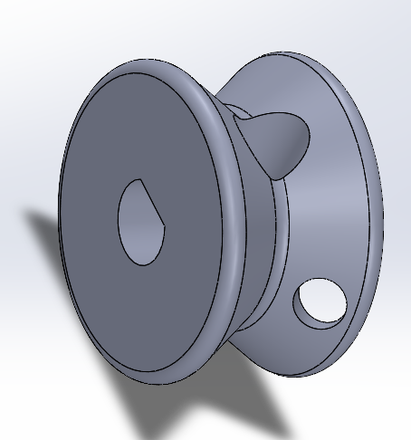
Pulleys
Pulleys were designed to fit on the motor shafts and needed to be able to attach the tether well. The pulleys press fit tightly onto the shaft. There is a hole for a screw to lock onto the shaft but the plastic threads do not hold well enough to do anything. The pulley has a hole to tie the tether into.
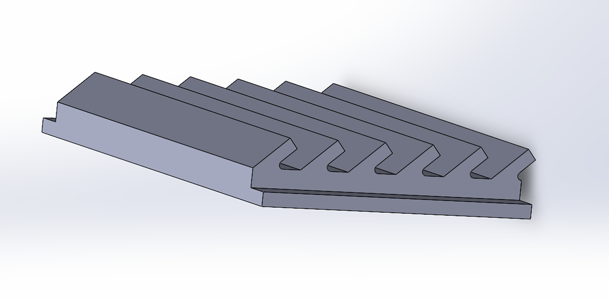
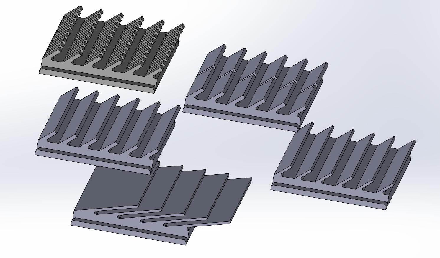
Friction Pad Design
Friction pads were designed that could be 3D printed to achieve directional friction. These were printed out of TPU. The designs all revolved around a sawtooth with differing lengths, thicknesses, and angles. This is still undergoing work to characterize what aspects of the pads affect motion, increase performance, and allow forward locomotion.
User Input
Previously, the robot was controlled by a timed sequence. This was easy to implement but without any speed control, the motors would get out of sync and it was hard to realign them. A way to control the robot live would make the testing and movement much easier.
An analog joystick was used for user input. A plastic joystick was fit to the small metal joystick piece, and a housing was made to hold the joystick and Arduino side by side.
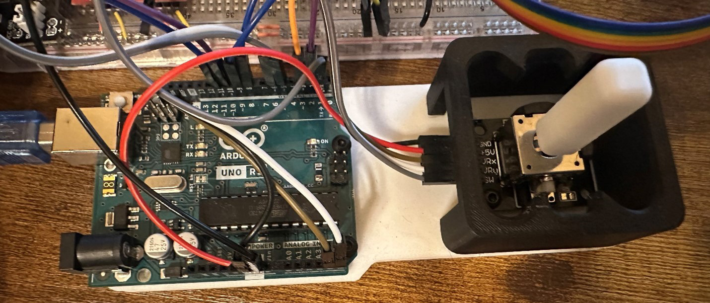
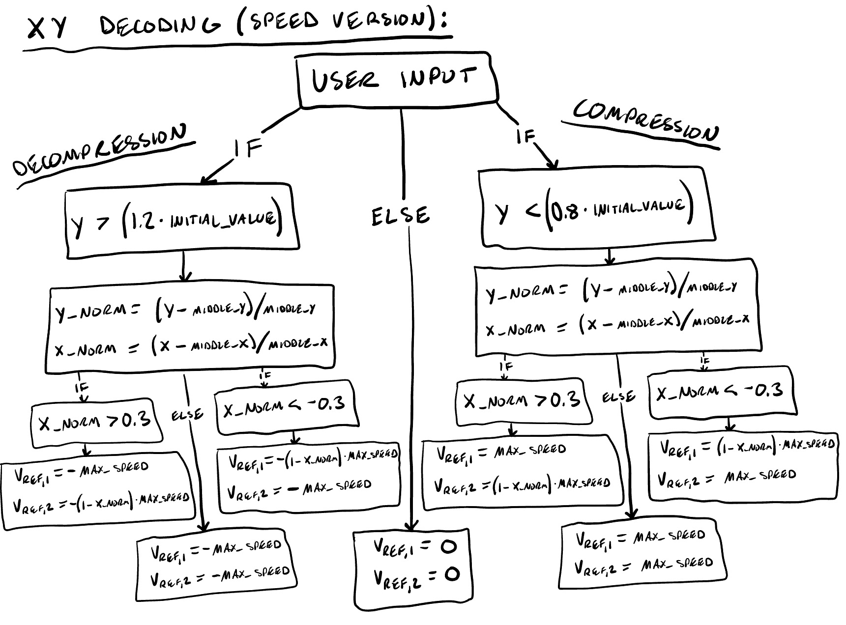
Pushing the joystick forward compresses both motors and vice versa. Pushing it to one side rotates a given motor depending on if its forwards or backwards.
Controller
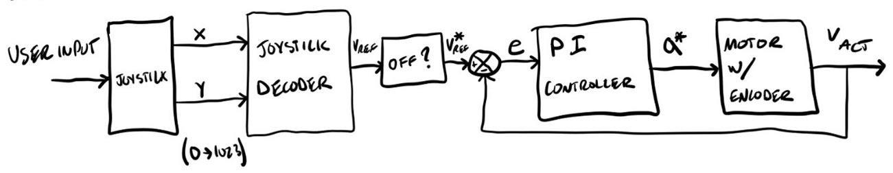
A speed-based PI controller was used to go to a specific speed based on how forward the joystick was. If the motors become off, the system corrects this until the motor’s angles are realigned.
Movement Results
Once the new robot was fully working, tests could be completed using different friction pads and worm angles. This is still undergoing work. Movement is very dependent on the ground surface: roughness and angle. With all the different variables that affect the motion, it is very difficult to understand what is doing what. Sometimes the robot will work as planned, sometimes won’t work at all, and sometimes will do the opposite of what is expected.
We are currently playing around with the worm angle by adjusting the tether connection point which changes the balance of moments about the center of action. This changes how the robot puts pressure into the pads. We are also trying an assortment of friction pad designs and where the pads sit relative to the mounts. Since they are friction fit into the mounts, they can be moved in and out of the mount to move the feet more or less outward.